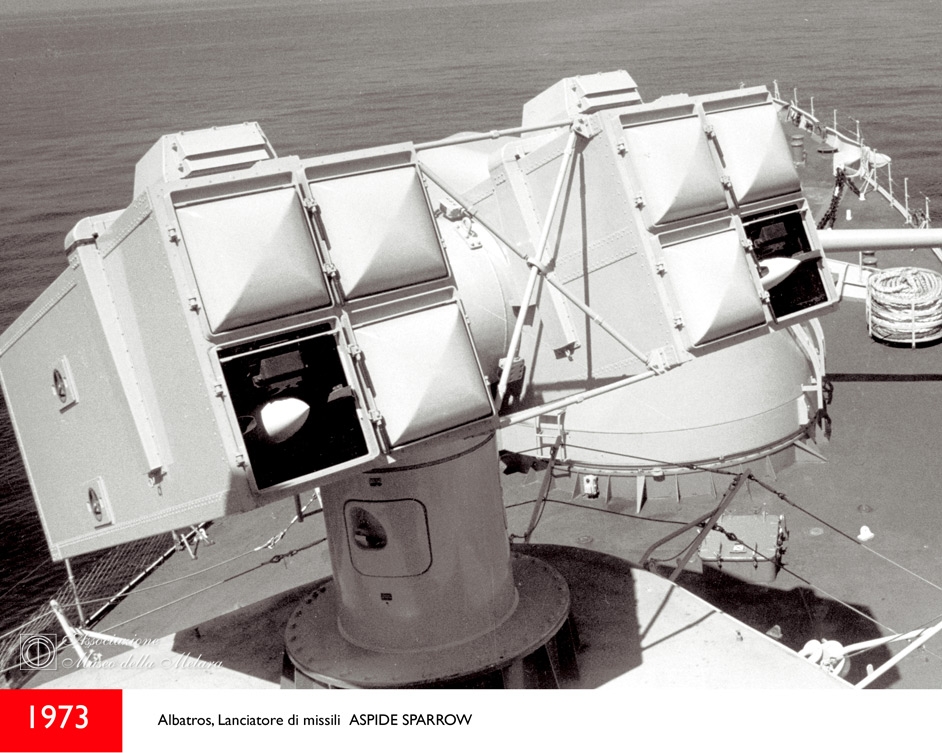
SISTEMA MBDA "ALBATROS" IMBARCATO
- Origine - Italia
- genere - Sistema SAM navale
- Servizio inserito - 1977
- Stato - In servizio
- Sviluppo - Primi anni '70
- Sviluppatore - Italia - Alenia
- Produzione - Fine anni '70 - presente
- Produttore - Italia - Alenia (ora MBDA)
- Utenti principali - Italia - Argentina - Venezuela.
Descrizione
L'Albatros è un sistema missilistico navale superficie-aria di origine italiana. È principalmente inteso come un sistema di difesa di punto per le fregate. Il design è molto simile a quello del sistema statunitense RIM-7 Sea Sparrow. Varie parti sono intercambiabili: è anche possibile lanciare missili Sea Sparrow con piccole modifiche.
Il missile Aspide ha sostituito lo Sparrow nel sistema SAM nel sistema imbarcato Albatros originariamente prodotta dalla Selenia utile come autodifesa di punto e protezione d’area. Il sistema è disponibile con tre versioni di launcher (quattro, sei e otto celle) per soddisfare i requisiti di allestimento di ogni nave.
Con il sistema potevano essere fornite due versioni di missili:
- l'ASPIDE standard per la difesa di punto;
- l’ASPIDE 2000 per la difesa d’area.
Il trasmettitore ad onda continua (CW) forniva la potenza RF necessaria per la guida missilistica irradiata verso i bersagli attraverso l'antenna del localizzatore Fire Control System.
Il sistema Albatros era asservito al radar di tiro Selenia RTN10XM Orion pulse-Doppler ed al RTN-12X Sirio a onde continue per il tracciamento e l'illuminazione del bersaglio.
I radar posizionati insieme funzionavano insieme; l'RTN-10XM era il primo modello Orion a utilizzare l'agilità di frequenza anziché la diversità di frequenza, e l'RTN-12X con l'indicazione del bersaglio mobile che fungeva da riempitore di gap di basso livello. La capacità di superare il disordine della costa era molto importante a causa delle operazioni costiere della Marina italiana in mediterraneo.
Il sistema missilistico Albatros doveva essere considerato come parte del sistema di difesa aerea della nave che si interfacciava con il sistema di controllo di tiro della nave. Il sistema prevede l'archiviazione, il lancio e la guida dei missili Aspide.
Il sistema missilistico Albatros fornisce il controllo per il lancio dei missili Aspide contro il bersaglio assegnato. Il sistema si interfaccia con il Gun Fire Control System (GFCS) attraverso l'unità di controllo della sezione missilistica. Questa unità contiene un computer ed esegue la supervisione e il controllo del funzionamento dell'intero sistema. L'energia CW per l'illuminazione del bersaglio e il riferimento ai missili, viene generata dal gruppo trasmettitore Cw e inserita direttamente nel gruppo della guida d'onda del sistema di tiro e fuoco attraverso l'antenna del radar. Il lancio dei missili è controllato dalla Console di controllo delle armi del GFCS associato mediante un pannello di controllo dei missili. Gli ordini iniziali al lanciatore vengono inviati durante la fase di acquisizione, per spostare il lanciatore in condizione di attesa nella direzione del punto futuro previsto del bersaglio. La massima velocità di fuoco è di un missile ogni 2,5 secondi.
Il funzionamento dei sistemi inizia quando gli obiettivi in arrivo vengono rilevati dal radar di tracciamento RTN 30X. Le informazioni sul bersaglio vengono quindi trasferite al sistema di controllo dell'arma integrato NA 30. Il sistema comanda al radar di illuminazione RTN 12X CW di illuminare il bersaglio e lanciare il missile. La testa di guida dell’Aspide riceve l'eco del bersaglio nel suo ricevitore anteriore e il segnale dell'illuminatore diretto dall’RTN 12X nel ricevitore posteriore. Nell'elaborazione dei due segnali, si ottiene il doppler target, che viene utilizzato per il rilevamento automatico della frequenza del range target.
Se il bersaglio emette un segnale di inceppamento per negare l'eco del bersaglio al missile, il sistema di guida passa alla modalità passiva Home-On-Jam. In questa modalità, il missile ricava le informazioni di guida dal segnale di disturbo emesso dal bersaglio, permettendo così di continuare con successo l'intercettazione con il bersaglio. Se il trasmettitore di disturbo è spento, il missile ritorna nuovamente alla modalità di homing semi-attiva.
La società Selenia costruì dieci sistemi Albatros per la Marina Militare Italiana, tutti gli incrociatori, i cacciatorpediniere e le fregate alla fine furono equipaggiati nel corso dei normali refit. Le prime due navi divennero operative con la M.M. nel 1976; inizialmente i sistemi utilizzavano il missile Sparrow; successivamente i lanciatori furono convertiti al missile italiano Aspide. Sarebbero stati necessari radar di potenza superiore per sfruttare la portata aumentata dell’Aspide, inoltre la Selenia era certa che il suo nuovo missile sarebbe stato efficace anche contro i missili antinave che viaggiavano a pelo d’acqua.
La Marina peruviana ordinò quattro sistemi Albatros e un secondo contratto di esportazione era in fase di negoziazione. Quest'ultimo ordine non faceva parte di un accordo "pacchetto" italiano, a differenza del contratto peruviano e dell'atteso ordine venezuelano. Almeno altre tre marine richiesero dettagli sui sistemi Albatros per soddisfare requisiti specifici.
Il sistema veniva offerto in due versioni, con controllo del fuoco a singolo e a doppio canale. La variante a canale singolo, destinata alle navi fino alle dimensioni della corvetta, veniva offerta ad un prezzo tra i $ 2-2 milioni ed i $ 2-3 milioni, incluso il lanciatore ed il controllo del fuoco per i missili e fino a tre lanciatori con due diverse caratteristiche balistiche, ma esclusi i missili e le armi stesse.
Nel 2019 il sistema era in servizio in 16 paesi in tutto il mondo, su varie classi di navi da guerra, dagli OPV fino ai cacciatorpediniere e alle portaerei.
L’Albatros è un sistema navale ben collaudato, per tutte le condizioni atmosferiche e altamente resistente all'ECM: progettato per contrastare aeromobili, UAV, elicotteri in mare, nonché missili anti-nave e barchini costieri.
Design
Il design dell'Albatros si basa sui missili Aspide, una variante migliorata del missile aria-aria AIM-7E Sparrow. Il lanciatore è il US Mk 29 octuple lanciato, utilizzato anche dal sistema Sea Sparrow. Per l'uso su corvette è stato sviluppato un lanciatore quadruplo più piccolo.
Guida
Il missile Aspide è un missile homing radar semi-attivo. Ciò richiede che il bersaglio sia illuminato da un radar di controllo del fuoco ad onda continua. Un singolo bersaglio viene ingaggiato alla volta.
Potenza di fuoco
Il sistema Albatros spara il missile Aspide, un missile homing radar semi-attivo. La portata massima è di 15 km e l'altitudine massima è di 6 km. Quattro o otto missili sono pronti per il lancio, a seconda del tipo di lanciatore. È possibile combinare il lanciatore di ottuple con un sistema di archiviazione e ricarica contenente altri 16 missili. Utilizzando il più capace Aspide 2000 la portata aumenta a oltre 25 km e l'altitudine massima è di 8 km.
Utenti
L'Albatros è stato adottato dall'Italia per l'uso su varie fregate. È stato anche un successo di esportazione. Il sistema Albatros è in uso con 16 nazioni ed è imbarcato su oltre 70 unità navali.
Descrizione generale:
- Origine: Italia
- Genere: Missile aria-aria
- Lunghezza 3,65 m
- Diametro 0,21 m
- Apertura alare 1,00 m
- Peso 230 kg
- Guida Homing radar semi-attivo
- Testata di guerra ad Alta frammentazione esplosiva
- Peso 33 kg
- Innesco Prossimità e fusibile di contatto
- Propulsione: Motore a razzo a propellente solido monostadio
- Massima velocità: 4.520 km / h
- Raggio d’azione: oltre 15 km (superficie-aria)
- Altitudine: 6 km (superficie-aria).
ENGLISH
DESCRIPTION
Albatros is a well proven, all weather and highly ECM resistant naval system designed to counter aircraft, UAVs, helicopters at sea, as well as sea skimming and diving anti-ship missiles and PGMs.
The system is available with three versions of launcher (four, six and eight cells) to suit ship fitting requirements.
Two missile versions can be supplied with the system:
- the standard ASPIDE for point defence
- the ASPIDE 2000 for local area or consort ship defence.
The Continuous Wave (CW) transmitter provides the RF power necessary for the missile guidance that is radiated towards the targets through the Fire Control System tracker antenna.
The system is in service in 16 countries worldwide, on various classes of warship, from OPVs up to destroyers and aircraft carriers.
Albatros shipboard SAM
Aspide replaced Sparrow in the Albatros shipboard SAM system which Selenia describes as being for self-defence and mutual protection, falling between point defence and area defence. The system is available with three versions of launcher (four, six and eight cells) to suit ship fitting requirements. Two missile versions can be supplied with the system: the standard ASPIDE for point defence; and the ASPIDE 2000 for local area or consort ship defence. The Continuous Wave (CW) transmitter provides the RF power necessary for the missile guidance that is radiated towards the targets through the Fire Control System tracker antenna.
Albatros uses Selenia RTN10XM Orion pulse-Doppler and RTN-12X Sirio continuous wave radars for target tracking and illumination. The co-located radars operate together, the RTN-10XM being the first Orion model to incorporate frequency agility rather than frequency diversity, and the RTN-12X with moving-target indication acting as a low-level gap filler. The ability to overcome land clutter is important because of Italian Navy operations near the Mediterranean shoreline.
The Albatros missile system is to be considered as a part of the ship's air defence system that interfaces with be ship's gunfire control system. The system provides for the store, launching and guidance of the Aspide missiles. The Albatros missile system provides control for the firing of the Aspide missiles against the assigned target. The system interfaces with the Gun Fire Control System (GFCS) through the Missile Section Control Unit. This unit contains a computer and performs the supervision and control of operation of the complete system. The CW energy for target illumination and missile reference, is generated by the Cw transmitter group and injected directly into the Gun Fire Control System waveguide assembly for radiation through the tracker antenna. Missile firing is controlled at the Weapon Control Console of the associated GFCS by means of a - missile control panel. Initial orders to the launcher are sent during the acquisition phase, for moving the launcher in the stand-by condition to the present point direction. The maximum firing rate is one missile every 2.5 seconds.
Operation of the systems begins when the incoming targets are detected by the RTN 30X monopulse tracking radar. The target information is then transfered to the NA 30 integrated weapon control system. The system commands the RTN 12X CW illuminating radar to illuminate the target and launch the missile. The Aspide missile seeker receives the target echo in its front receiver and the direct illuminator signal from RTN 12X in the rear receiver. In processing the two signals, there results target doppler, which is used for automatic target range rate tracking.
If the target radiates a jamming signal to deny the target echo to the missile, the guidance system switches to the passive home-on-jam mode. In this mode, the missile derives the guidance information from the jamming signal emitted by the target, thus allowing it to successfully continue the intercept with the target. If the jamming transmitter is turned off, the missile switches back to the semi-active homing mode again.
Selenia built ten Albatros systems for the Italian Navy, all cruisers, destroyers and frigates eventually being equipped during the course of normal refits. The first two vessels became operational with the weapon in 1976; the systems used Sparrow at first, later being converted to Aspide. Higher-power radars may be necessary to take advantage of Aspide's increased range, and Selenia is hopeful that its new missile will be effective against sea-skimmers.
The Peruvian Navy ordered four Albatros systems and a second export contract is in the final stages of negotiation. This latter order is not part of an Italian "package" deal, unlike the Peruvian contract and the expected Venezuelan order. At least three other navies asked for details of Albatros to fill a specific requirement. The system was offered in two versions, with single- and double-channel fire-control. The single-channel variant, intended for ships down to corvette size, was offered at between $2-2 million and $2-3 million—including the launcher and fire-control for the missiles and up to three guns with two different ballistic characteristics, but excluding the missiles and guns themselves.
By 2019 the system was in service in 16 countries worldwide, on various classes of warship, from OPVs up to destroyers and aircraft carriers. Albatros is a well proven, all weather and highly ECM resistant naval system designed to counter aircraft, UAVs, helicopters at sea, as well as sea skimming and diving anti-ship missiles and PGMs.
CHARACTERISTICS:
- Length: 3.7 m
- Diameter: 234 mm
- Range: In excess of 25 km
- Speed: High supersonic.
Well proven, all weather and highly ECM resistant naval system designed to counter aircraft, UAVs, helicopters at sea, as well as sea skimming and diving anti-ship missiles and PGMs. The system is available with three versions of launcher (four, six and eight cells) to suit ship fitting requirements. Two missile versions can be supplied with the system: • the standard ASPIDE for point defence • the ASPIDE 2000 for local area or consort ship defence The concept of the ALBATROS system is to add missile capability to naval OTOMELARA 76/62 gun fire control systems for combined use of missiles and guns, without duplicating the tracking sensors or the operator’s work-station. The ALBATROS system can be integrated with the NA-30 type Fire Control System based on the ORION/RTN-30X tracking radar in single or double tracker configuration.
The Continuous Wave (CW) transmitter provides the RF power necessary for the missile guidance that is radiated towards the targets through the Fire Control System tracker antenna. The system is in service in 16 countries worldwide, on various classes of warship, from OPVs up to destroyers and aircraft carriers.
Aspide missile for “ALBATROSS SYSTEM”
Aspide missile (the Italian name for the adder) is an Italian medium range air-to-air and surface-to-air missile produced by Selenia (now part of the Alenia consortium). It is provided with semi-active radar homing seeker. It is very similar to the American AIM-7 Sparrow, using the same airframe, but at the moment of its introduction, the Aspide was provided with monopulse guide instead of the conic scan, which made it more resistant to ECM and more precise. This innovation appeared on the Sparrows only with the late AIM-7M version. Closed-loop hydraulics were also substituted for Sparrow's open-loop type, which gave Aspide better downrange maneuverability.
This resemblance, and the fact that Selenia was provided with the technology know-how of the AIM-7 (around 1,000 of which it had produced under license), has generally led non-Italian press to refer to the Aspide as a Sparrow variant. However, the Aspide had original electronics and warhead, and a new and more powerful engine. Even the control surfaces are different, replacing the original triangular wings, fixed in the air-to-air and instead foldable in the surface-to-air version, to a newly designed common cropped delta fixed version.
Design
Aspide, in its various versions, was used both in the air-to-air role, carried by Aeritalia F-104s in the apposite versions F-104S and F-104ASA, and in the surface-to-air naval role. In the latter role it has been replaced by the MBDA Aster. Naval Aspide launchers can be adapted to fire the Sparrow by merely switching a single circuit board.
In the mid 1980s, China imported a small batch of the Aspide Mk.1 from Italy, then signed an agreement with Alenia to produce the missile locally under license. In 1989, China produced its first batch of Aspide Mk.1 missiles using imported parts from Italy. However, due to the European Union arms embargo imposed after the Tiananmen Square incident, China was unable to purchase additional Aspide kits. China subsequently developed its own missile family based on the Aspide Mk.1, with surface to air versions designated as the LY-60, and an air-to-air version designated as PL-10.
The rocket engine of the Aspide is produced by Turkish missile manufacturer Roketsan.
Variants
- Aspide Mk.1 - Similar to AIM-7E, with Selenia monopulse semi-active seeker and SNIA-Viscosa solid-propellant rocket motor. This version was popular with export customers, and sold to 17 countries.
- Aspide Mk.2 - Improved version with active radar-homing seeker. Development was shelved in favor of better missiles, such as the AIM-120 AMRAAM.
- Aspide 2000 - Surface-to-air version of the Aspide Mk.1, used on Italian Army Skyguard and Spada air-defense systems.
Operators:
- Argentina - MEKO 360 ships, 150 Mk1 ordered in 1979 and delivered in 1983-1984
- Brazil - 100 Aspide 2000 ordered in 1996 and delivered in 2001-2004 - São Paulo aircraft carrier, Niterói class frigates
- People's Republic of China - 90 Aspide Mk.1 ordered in 1986 and delivered in 1987-1991. Technology used in development of LY-60/PL-10
- Cyprus - 130 used in existing Skyguard system; ordered in 1991 and delivered in 1991-1992 (deal worth $114 m included 12 launchers)
- Ecuador - 50 used on Esmeraldas Class Corvette (variant of Fincantieri Tipo 550); ordered in 1979 and delivered in 1982-1984
- Egypt – 72 used on Descubierta (Abu Qir) class corvettes; ordered in 1983 and delivered in 1984; Aspide 2000 (36 Systems)
- Greece - 75 for Elli-class frigates (variant of Kortenaer-class); ordered in 1980 and delivered in 1981-1982
- Italy - used on-board F-104S; used on 7 Spada SAM batteries; used on 24 Skyguard SAM batteries; used on 32 naval Albatross Mk2 SAM system
- Kuwait - 320 ordered in 1988 and delivered in 1988-1997 for Skyguard Amoun SAM System; 175 Aspide 2000 ordered in 2007 and delivered in 2008-2010 part of 565 $ m deal, for modernization Aspide; 250 Aspide 2000 ordered in 2007 and delivered in 2008-2013 part of $65 m deal for Skyguard AD systems.
- Libya - 8 ordered in 1978 and delivered in 1983 for use on Albatross Mk-2 SAM on modernised Libyan frigate Dat Assawari
- Malaysia - 18 ordered in 1995 and delivered in 1997 for Laksamana Class corvette
- Morocco - Used in the frigate 501 Lt. Col. Errhamani (Descubierta); 40 ordered in 1977 and delivered in 1983
- Nigeria - 25 Aspide MK.1 ordered in 1977 and delivered in 1982 for Meko-360 Aradu frigate; other 10 Aspide MK.1 ordered in 1982 and delivered in 1983
- Pakistan - 750 Aspide 2000 for ground-based air defence system (10 batteries Spada 2000) ordered in 2007 and delivered in 2010-2013 part of 415 m Euro deal [5]
- Peru - 150 ordered in 1974 and delivered in 1979-1987 for use on Lupo (Carvajal) class frigates
- Spain - 200 ordered in 1985 and delivered in 1987-1989 part of $230 m deal for 6 Spada SAM system; 51 Aspide 2000 ordered in 1996 and delivered in 1997-1999 for 2 Spada 2000 SAM systems
- Thailand – 24 ordered in 1984 and delivered in 1986-1987 for use on Ratanakosin Class corvettes; 75 ordered in 1986 and delivered in 1988 for use by Royal Thai army on 1 Spada SAM system
- Turkey - 144 ordered in 1986 and delivered in 1987-1989 for MEKO 200T (Yavuz class) frigate; 72 ordered in 1990 and delivered in 1995-1996 for MEKO 200T-2 (Barbaros class) frigate
- Venezuela - 100 ordered in 1975 and delivered in 1980-1982 for use with Albatross SAM system on Lupo Class frigates.
(Web, Google, weapon systems, globalsecurity, Wikipedia, You Tube)